
Our GateRodders concept is to make functionally complete mechanical logic gates that can be used to introduce the basic concepts of digital logic design in a very concrete way. Although we have played with various methods to make mechanical gates (especially designs using marbles), the inspiration for using rod positions to represent logic values came from this video by Baptiste Cavin. A rod at logic 1 extends 5mm forward of the position it has when at logic 0. The advantage is that this use of rods allows complete gates (or even complex mechanical circuits) to be quickly 3D-printed fully assembled -- and we have been able to shape the gates like their standard logic symbols.
The designs here were used to produce the NOR gates we handed out in our research exhibit at the IEEE/ACM SC17 conference. We expect to post more versions shortly that will be preferable for further use; be warned that later GateRodder designs might not be interoperable with this first one.
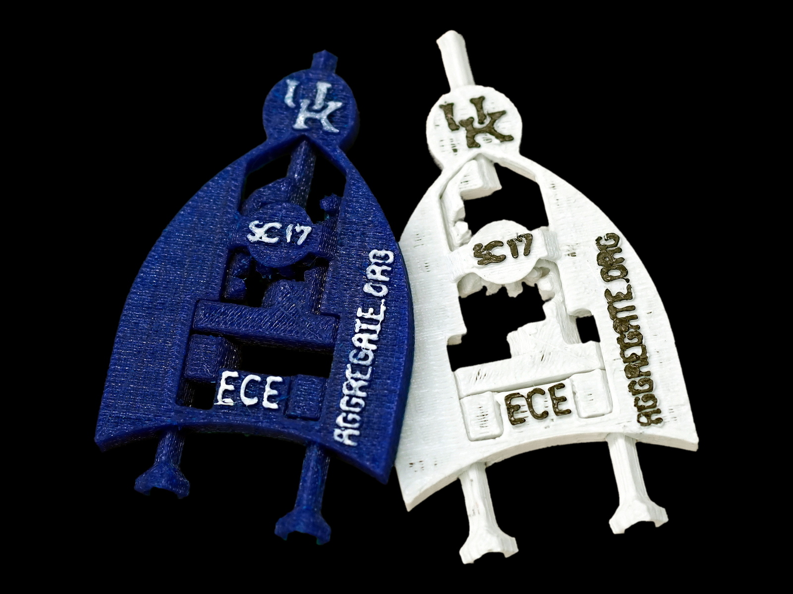
To operate this mechanical NOR gate, begin by pulling the output rod forward to the logic 1 position, which should also force the two input rods to be reset their logic 0 position. Pushing in either or both of the input rods (making them go from logic 0 to 1) will push the OR pusher block forward, causing the gear to pull the output rod backward to the 0 position. Generally, the gear operation is a little rough, but does get smoother with continued operation. In the photo, the blue NOR gate has inputs of 1 and 0, with an output of 0, and the white NOR gate has inputs of 0 and 0, with an output of 1.
Currently, the part to make is a working, 3D-print-assembled without supports, mechanical NOR gate. There will be others. All will be posted at ThingiVerse as well as here; the SC17 NOR design is Thing 2654691.
This design has been printed successfully using various materials (PLAs) on a variety of MakerGear M2 & M3 and Wanhao i3 versions; we printed them in our SC17 exhibit on an original Wanhao i3. However, as for nearly any print-assembled design with moving parts, it is critical that the tolerances match what your printer is capable of; the difference between parts being bonded together and being too loose is fractions of a mm in the gaps between parts.
The four different STL versions are:
These versions differ only in the general part tolerances used, with larger ones corresponding to larger t values. The one most likely to print with minimal grief is gaterodders20171101t2.stl, but well-calibrated machines printing with shorter layer heights might find gaterodders20171101t1.stl works better. Don't print with an extra-tall first layer, and also be aware that a hot end that has worn a little wider can cause problems too -- recognizing that one of our M2 had worn from being 0.35 to about 0.38 made a huge difference is print success rate.
You might also have noticed that the NOR gate prints at a 45-degree angle. This is because we used cura to do the slicing and the 45-degree angle makes the infill structure line-up lengthwise with the part, which seems to work slightly better than other angles.
To print as fast as possible, we used 0.25mm layers, 20% infill, just one shell on the vertical and two shell layers on the horizontal surfaces. However, dropping to 0.15mm layers, 40% infill, and several shells does improve part appearance. Just be warned that thicker shells and/or heavier fill might slightly change tolerances. Do NOT use a brim -- there is a tiny brim in the design to keep the output pin from lifting, but adding more brims could make brim removal a nightmare.
Although there are no support materials, there is a tiny square brim on the front of the output bar -- clip that off. If the tolerances are right, everything should just work. The gear is the most common point of unwanted bonding; if it sticks, you can gently grab the gear from underneath and rotate it with a pair of longnose pliers to break the bond. Similarly, the rods may be partially stuck in their channels, in which case you can usually free them by gently wiggling the rods or, in the worst case, separating the rods from their channels using a razor blade.
After printing, we felt the text and logos would look better highlighted. Thus, we used either paint or a permanent marker to color the raised portions.
A functionally complete set of logic gates is a set of gate types that allows one to implement any arbitrary logic function. Perhaps the best known set is {AND, OR, NOT}. However, there are single gate types that are sufficient. The best known are NAND (not AND), NOR (not OR), and MUX (a 1-of-2 multiplexor). Although we intend to eventually have GateRodders implementations of all the common gate types, we wanted to start with one gate type that is functionally complete, and NOR was the easiest of those to implement.
Making digital logic gates that can be 3D-printed fully assembled without any unsupported spans is hard. Making them small enough to print quickly while keeping within tolerances that most printers can meet is even harder... and making them shaped like their standard logic representation is an annoyingly awkward constraint. It took nearly 3 weeks and a couple dozen fundamentally different designs before settling on the current GateRodders design for SC17.
A NOR gate is fundamentally a NOT gate imposed on the output of an OR. The input and output rods are trapped structures with a 45-degree angled top that allows bridging over them without an unsupported span. The OR logic is very easy to implement by having a pusher block that spans the (two or more) input rods such that pushing any rod pushes the block. The NOT is significantly more complex to build because it needs to reverse the direction of motion. After trying various pivot structures, we settled on a double rack-and-pinion derived from janssen86's Gear Rack and Pinion; the (rather tiny) gear core serves primarily to keep the pivot point from moving, while the herringbone pattern of the gear teeth keeps the gear centered as it engages the racks. The self-supporting bridge to hold the core is raised because it needs that thickness, while the surrounding portions of the gate were kept thinner to reduce print time. The one disappointing issue here is that this NOR gate requires manual reset. Some of the alternatives we tried incorporated 3D-printed springs to reset the gate to the 0-inputs, 1-output state, but those springs didn't work well at this tiny scale. A rubber band easily could be added to pull the pusher block back, but that would add an assembly step. We had hoped that gravity would be sufficient to reset everything if the gate is held pointing up, and sometimes it is, but the double rack and pinion typically has too much friction. This is one of several reasons we do not consider the SC17 version to be the final version....
![]() The only thing set in stone is our name.
The only thing set in stone is our name.